1981 Photo Album by Tom Kennedy
Thanks for all these photos Tom, they are great. Also, thanks to Tim Schuyler who scanned them for us. If the picture doesn't fill in for you, try a right click on the picture and select "show picture". There are a gzillion pictures here!
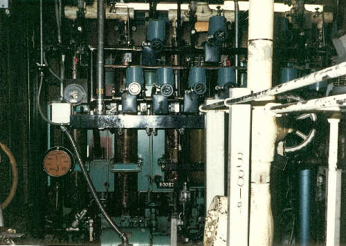
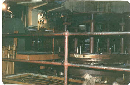
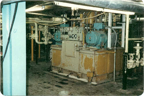
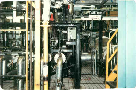
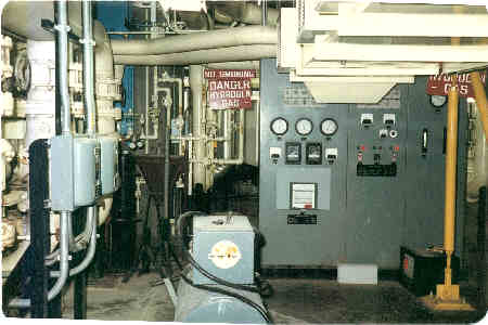
The hydraulic power (91) system for the plant on level 1 of the reactor building.
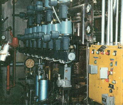
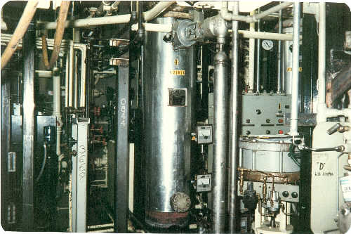
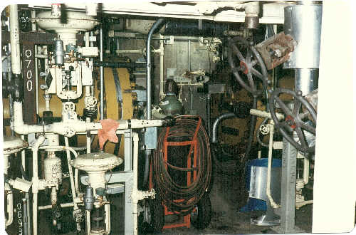
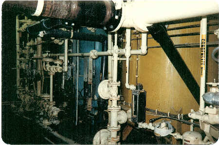
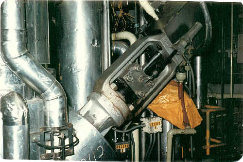
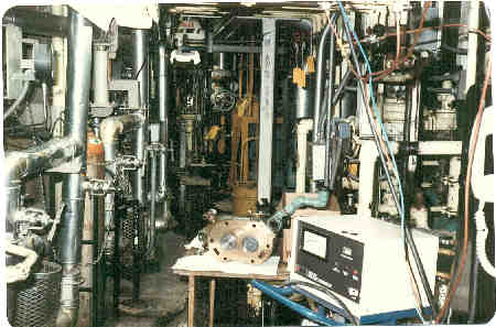
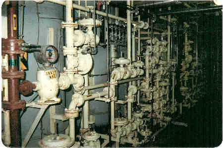
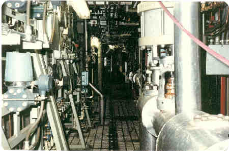
Loop II of the 91 system or hydraulic system. This hydraulic pressure was used to operate many of the larger valves in the reactor building and turbine building of the palnt. This system was always very difficult to work on because there wasn't enough space allowed to get to many of the components--not to mention trying to remove them to work on them!
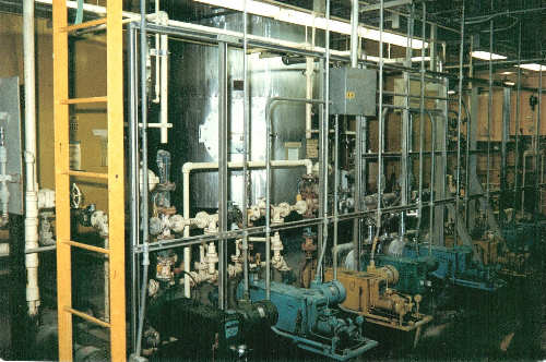
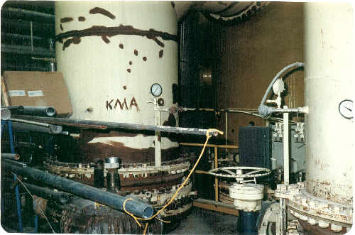
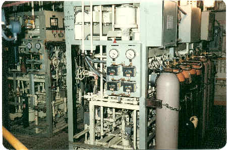
These are the ammonia, caustic and acid storage tanks in the demineralizer room along with their associated pumps. This area was used for water treatment and makeup. Level 5 in the turbine building.
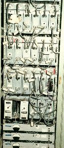
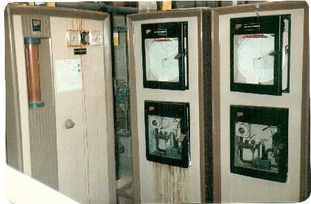
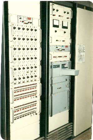
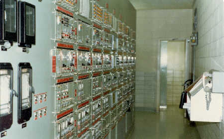
This is a rack of signal conditioning equipment manufactured by Foxboro and Moog. Tbere were roughly two dozen racks of equipment similar to this associated with the controls of the plant.
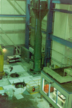
This is the auxilery transfer cask on the refueling deck of the reactor building. The fuel handling machine control room is visible on the lower right of the picture.
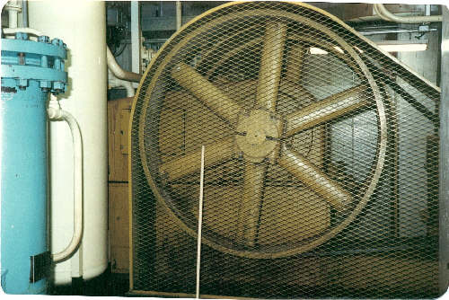
Main flywheel for our helium compressor called "Big Thumper". Big Thumper was used to maintain the pressure of the reactor.
Big Thumper was located on level one of the reactor building.
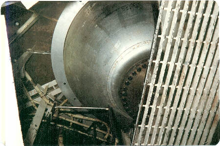
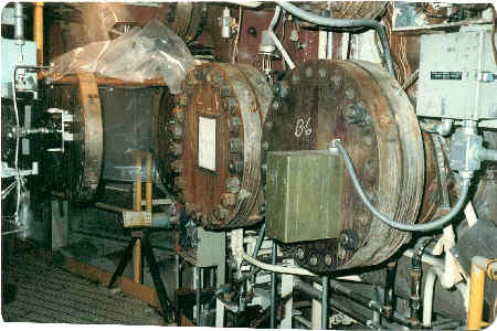
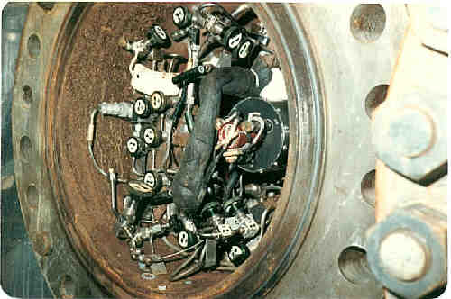
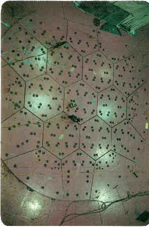
Reactor bottom head access plug.
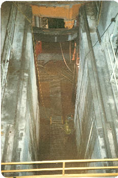
Left: This is the "keyway", sometimes called the "snake pit", the lowest point in the reactor building. The reactor building was built on bedrock and extended 5 floors below ground level.
RIGHT: is the bypass flash tank drag valves.
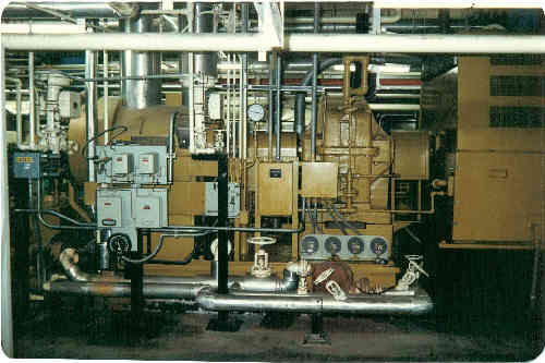
This is the orginal buffer helium dryer. In 1983 we completed a loop split change and installed two new dryers. Level one of the reactor building.
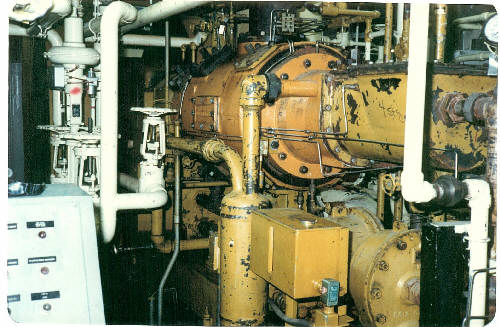
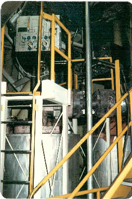
For a lot of these pictures--"ya kinda had to be there" but the yellow equipment is one of 4 buffer helium recirculators.
The bottom of "C" helium circulator.
These are the chlorine injectors for the service water tower and the chlorine monitors for the circulating water and service water towers. Looks pretty rough but it worked!
This is the chlorine evaporator and the injector for the circ water tower.
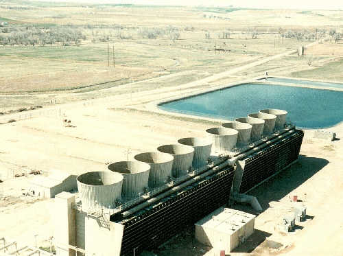
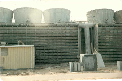
This is a shot of the circulating water tower from the roof of the reactor building. The circulating water is what is used to cool the steam, once it is used in the main turbine generator, back to water. This allows the steam water cycle to start over again.
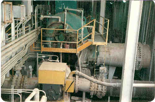
Circulating water pumps "B" and "C" of 4 pumps. These pumps pump the water from the coolin tower to the condenser located right under the main steam turbine.
Circ water tower showing one of the main pipes coming from the condenser in the plant. This pipe is 84" in diameter!
Circ water piping at the condenser in the plant turbine building, level 5 (ground level).
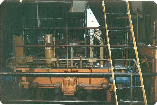
The helium circulator handling machine, or Rucker Unit, located on level 1 directly under the PCRV for pulling helium circulators out of the reactor for maintenance.
Another shot of the Rucker unit.
This part of the condensate polisher resin regeneration skid showing the resin storage tank and the "anion" tank and some of the piping.
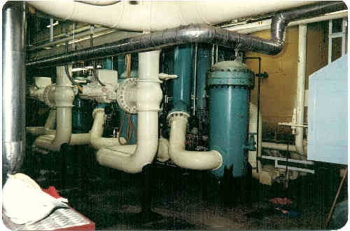
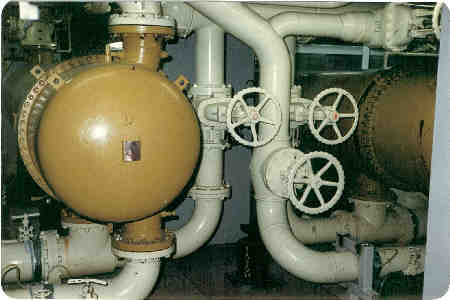
This is the condensate polisher area. The yellow tank is one of three polishers and the blue tank is a resin trap. Level 5 of the turbine building just north of the demineralizer room.
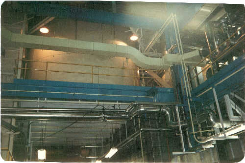
This is another one you kinda needed to be there to visualize this shot. It's taken in the railroad bay near the auxiliery boiler room and looking up to level 6 at the south condensate storage tank.The building steam heating system main control valves are in the upper right.
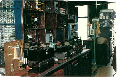
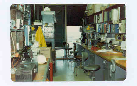
Work bench in the I&C Maintenance or "Results" shop.
"D" helium circulator "speed" valve located on level 3 of the reactor building.
These two shots are taken in the Data Acquisition and Storage (DAS) room on level 2 of the reactor building. This equipment was designed by General Atomics and monitored temperatures and stresses of the prestressed concrete reactor vessel (PCRV). This was one of the few places in the reactor building that was kept cool when the plant was running!
The hydraulic system for the main turbine generator (EHC system). Level 5 of the turbine plant.
Boiler Feed pump "B" was the only electric drive BFP we had. Level 5 in turbine bldg.
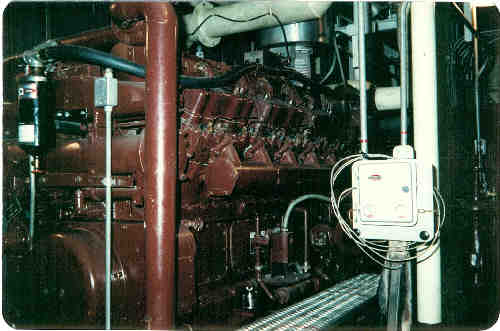
One of our emergency diesel electric generators---for when the lights go out!
Feedwater heater 5 on level 6 of the turbine building. A feedwater heater uses a little steam from the steam turbine to preheat the condensate on it's way to be made into steam in the reactor steam generators.
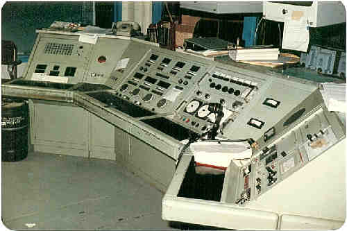
This is the fuel handling machine control console located on the fuel deck, or level 11, in the reactor building. The fuel handling machine was a huge robotic like device used to load and unload fuel and well as service equipment inside the reactor vessel.
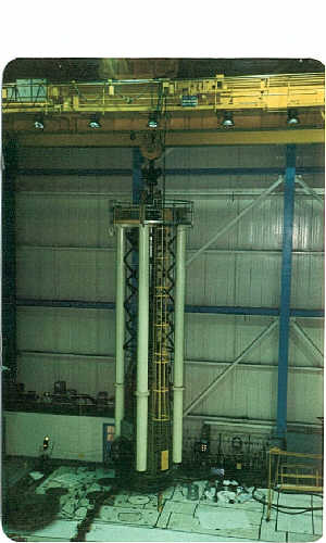
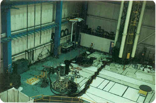
The fuel handling machine (FHM) is shown here on the left. It was moved around with the huge overhead trolly crane shown. The picture above shows the "trailing cables" that connected to the control console and computer.
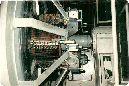
This is the main generator exciter showing the exciter brushes. Level 7 of the turbine building inside the generator compartment.
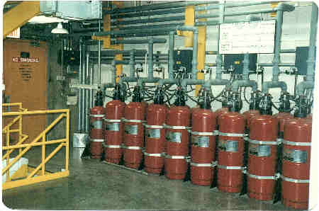
This is the Halon fire supression system for the auxiliery control room on level 6 of the turbine building near the steam/water sample sink.
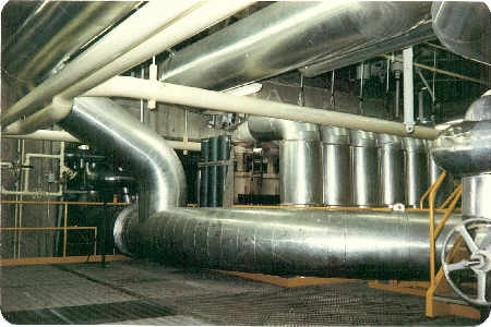
Main turbine hot reheat bypass valves. Level 6 of turbine building.
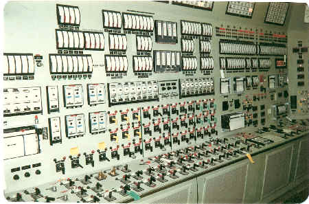
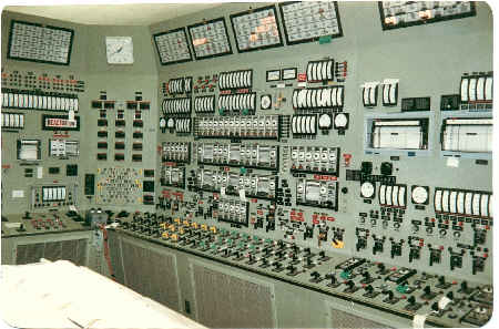
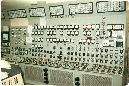
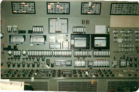
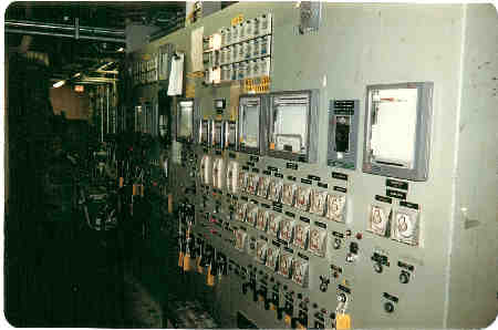
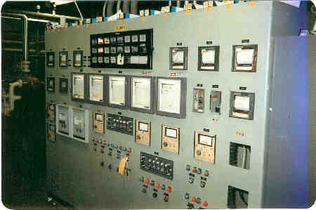
I-9301, 2, & 3. circulator auxiliery and reactor controls.
I-9303, 4 and 5. Reactor, circulator and boiler feed pump controls.
I-9306 Boiler feed pump and turbine controls
I-9306 Turbine generator, switchyard, and miscellaneous controls.
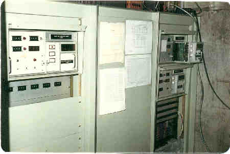
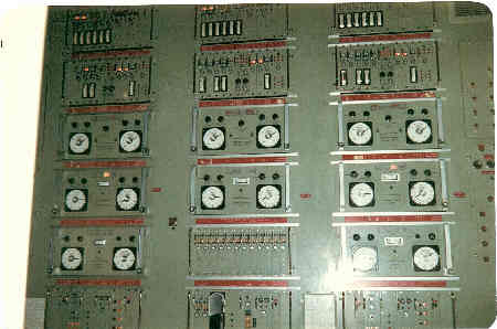
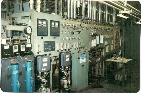
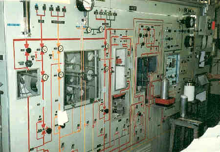
Reactor plant protective system--two out of three logic. Also, the power channels.This is all Gulf General Atomics designed and built stuff.
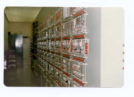
I-9310 the plant protection system or PPS. 2 out of 3 logic.
The PPS from the other direction.
Instrumentation and moisture monitor penetrations into the PCRV on level 5-1/2 of the reactor building.
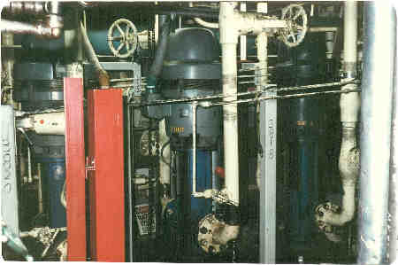
Loop I bearing water pumps on level 1 of the reactor building near the hydraulic supply system. The helium circulators had water bearings and these are the pumps that supplied the pressure.
This is a shot on level 1 of the reactor building on the north side near the RIX compressors.
Reheat steam attemperator area in reactor building level 3.
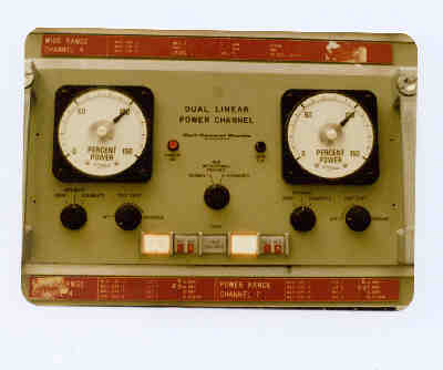
Dual Linear Reactor power channels--yes, we did make it to 100% power a time or two!
Main steam stop valves on level 6 of the turbine building. 2400 psig and 1000 deg F.
This is the demineralized water make-up treatment skid in the demin room on level 5 of the turbine building. This is make-up train B.
A moisture monitor penetration showing a single moisture monitor. Some penetrations had two monitors. This was not a fun place to work! Level 5-1/2 in the reactor building.
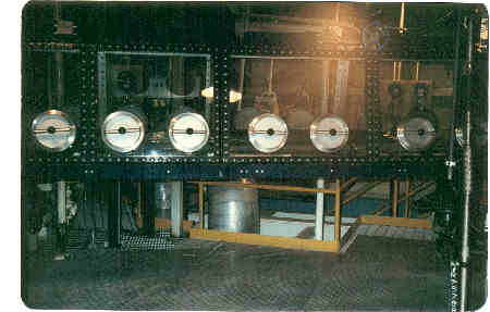
Plate out probe glove box in reactor building.
Demin Room control panel.
Primary Coolant gas chromatagraph in the AI room. Level 7 of the reactor building.
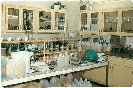
Part of the radiochemistry lab.
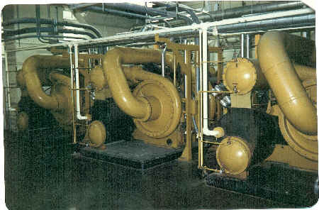
Reactor building chillers A, B and C. We had 5 Trane chillers to keep the reactor building bearable during power operation.
Reactor missile shields on the top of the reactor. Fuel deck..
The reserve shutdown system. This system was designed to bring the reactor into a safe shutdown in the event the control rod drives would fail to insert.
The Results shop.
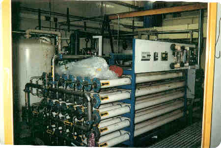
This is the reverse osmosis unit. It was the start of our water making process. The water used had to be incredibly pure to prevent anything from plating out inside the nuclear steam generators in the reactor.
Level 2 in the reactor building. Many tall people were made shorter here!
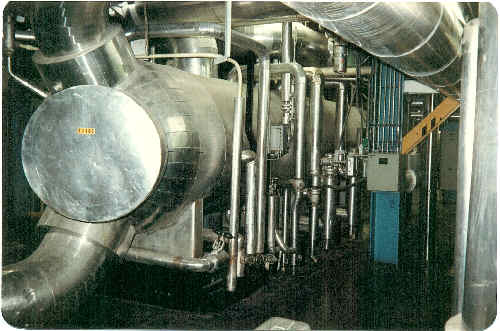
Reactor vessel cooling water heat exchanger.
Steam and water sampling sink located on level 6 of the turbine building.
Sample sink intrumentation.
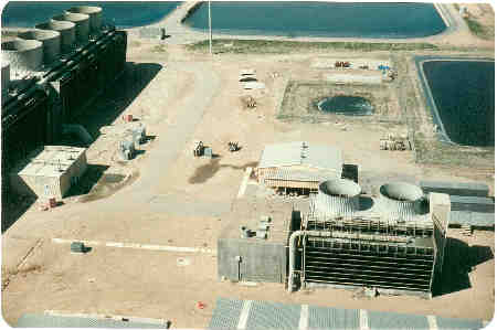
Service water cooling tower in lower right foreground. Circ water make-up ponds in the top area of the photo and the end of the circ water cooling tower on the upper left. The building nearly in the center of the photo is called the "Chem Building" and is where the chlorinators and other water treatment injection pumps are located.
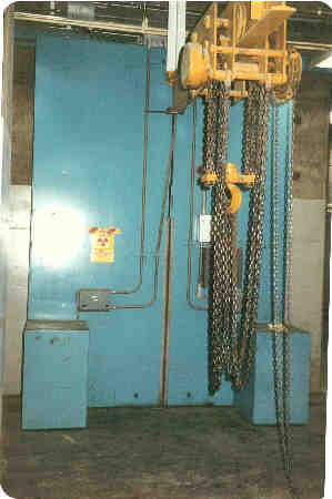
Shielded doors to the gas waste compressors
Stator coolant water control panel on level 5 of turbine building.
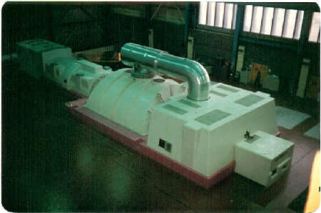
Main steam turbine on level 7 of the turbine building. This turbine is still in use today, acception steam from our heat recovery steam generators of the new natural gas fired plant. This is a GE turbine rated at 330 mW.
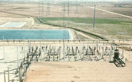
This is a shot looking to the south from the turbine building roof showing part of the main switchyard, transmission lines and evaporative ponds.
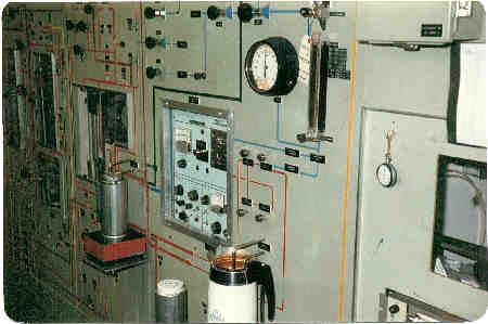
Valving panel in the analytical instrumentation room.
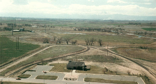
View to the west from the reactor building roof showing the visitors center, train tracks, St. Vrain river, and the Rocky Mountains barely visible in the distance.
Thank you Tom Kennedy for sharing these wonderful pictures with us!
